Port + Wharf Autonomy

Autonomousmobilityforthemodernterminal.

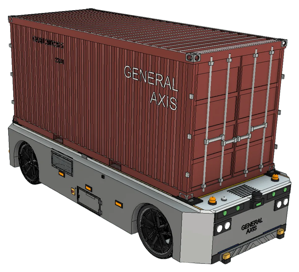
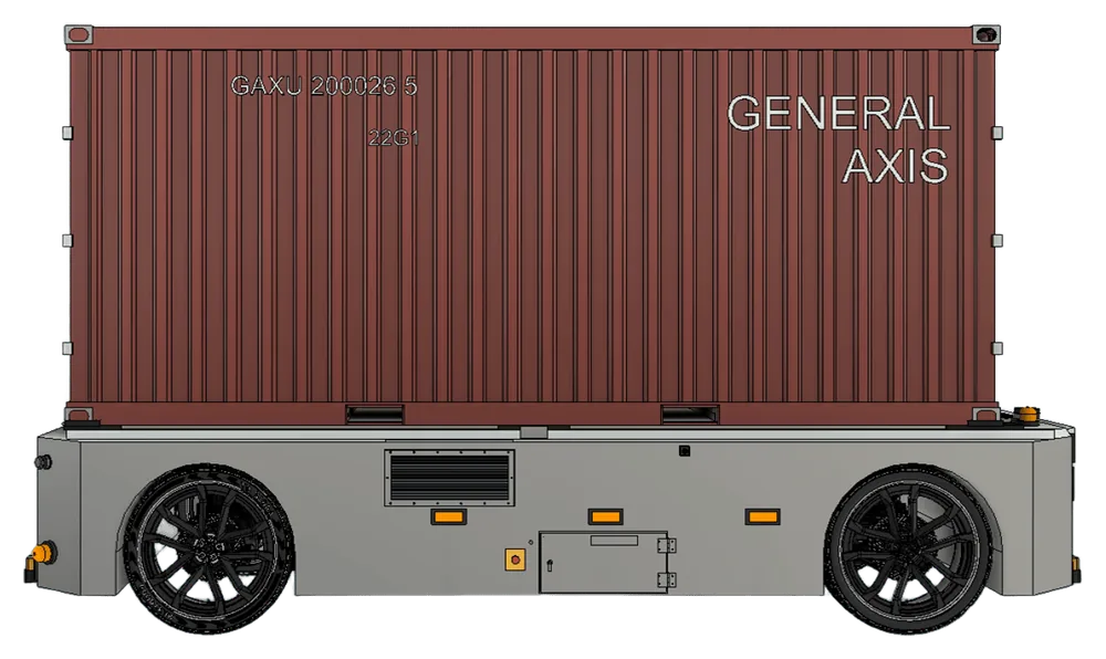
General Axis engineers autonomous vehicle platforms and AI control systems for cargo movement, berth-side operations, and terminal logistics, with safety, uptime, and throughput as core design constraints.

0.0%

Target platform availability for mission-critical terminal operations.

<0ms

Control-loop responsiveness for precision navigation and docking.

0/7

Continuous operations model with fleet monitoring and failover.

0cm

Repeatable docking precision at transfer bays and service stations.

Our Mission

Ports move the world's goods, yet much of that work is still dangerous, repetitive, and constrained by labor. We build autonomy that makes terminals safer and more productive.

General Axis is an autonomy company focused exclusively on the port and wharf environment. We combine automotive-grade sensing, real-time control, and fleet-level orchestration into vehicles that operate around the clock in some of the most demanding industrial settings in the world.

Our approach is safety-first and deployment-driven. Every system is engineered to fail safe, validated under real operating conditions, and rolled out in stages alongside the people who run the terminal, not as a replacement for their expertise, but as a force multiplier for it.

Read our full mission
The Autonomy Stack

A full-stack platform, from sensor to fleet.

Four tightly-coupled layers turn raw terminal sensing into coordinated, safe, around-the-clock vehicle operation.

01

Perception

Sensor-fusion stack for obstacle classification, pedestrian awareness, and dynamic risk handling across mixed-operability zones.

02

Planning

Mission orchestration that assigns routes and priorities to autonomous assets based on berth operations and turnaround targets.

03

Control

Sub-20ms control loops for precision maneuvering near vessel edges, crane zones, and centimeter-level docking alignment.

04

Fleet Ops

Supervisory telemetry tracking fleet state, route adherence, utilization, and predictive maintenance signals in live operations.

How We Deploy

From survey to autonomous operation.

A staged path that de-risks deployment and keeps humans in the loop until the system has earned trust.

1

Site assessment

Survey wharf lanes, staging zones, and handoff points; build a high-fidelity digital map of the terminal.

2

Integration

Mount sensors, calibrate the autonomy stack, and connect to existing yard and berth scheduling systems.

3

Supervised autonomy

Run staged rollouts with human oversight, validating safety envelopes against real operating conditions.

4

Full deployment

Hand over to continuous autonomous operation with 24/7 fleet monitoring and failover readiness.

Robot Network

Research behind coordinated fleets.

A terminal runs on many vehicles acting as one. Our research focuses on how robots sense, decide, and stay coordinated, even when the network is imperfect.

01

Communication as a Sensor

We treat the wireless link itself as a sensing modality. Signal strength, latency, and connectivity between vehicles reveal relative position, network topology, and coverage gaps. The fleet's radio becomes another way to perceive the terminal.

02

Multi-Robot Sequential Decision Making

Fleets reason over time, not just the next move. We model task allocation, routing, and berth handoffs as sequential decisions under uncertainty, so dozens of vehicles plan cooperatively toward turnaround targets instead of competing for the same lanes and bays.

03

Resilience in Multi-Robot Coordination

Coordination has to survive dropped links, sensor faults, and degraded vehicles. Our methods keep the fleet safely productive when communication is lost or assets fail, so the system slows down gracefully instead of stalling.

Sensor Suite

Redundant, multi-modal sensing.

Every vehicle carries overlapping vision, LiDAR, radar, and localization sensors so no single failure or weather condition can blind it. Each modality covers the others' weaknesses.

01 Vision

Surround Camera Array

Configuration
8× wide-FOV, 360° ring
Resolution
8.3 MP (3840×2160)
Frame rate
30–60 fps, HW-synced
Dynamic range
120 dB HDR

Primary semantic vision: worker and pedestrian detection, ISO container-code OCR, lane and edge markings, and signal recognition across the full ring around the vehicle. HDR holds detail through the harsh sun-to-shadow transitions of quay-side operation.

02 Vision

Long-Range Telephoto

Field of view
30° forward cone
Detection range
≥ 200 m
Resolution
8.3 MP
Fusion
Forward LiDAR + radar

Early detection of vehicles, cranes-in-motion, and obstructions far down a transit corridor, giving the planner the lookahead needed for smooth speed control at lane speed.

03 Vision

Stereo Depth Pair

Output
Dense disparity / depth
Range
0.5–40 m
Baseline
Fixed calibrated stereo
Use
Near-field docking

Passive metric depth for close-quarters maneuvers, verifying clearance during reversing, bay approach, and alignment where centimeter accuracy matters.

04 LiDAR

360° Mechanical LiDAR

Channels
128 beams
Range
Up to 245 m
Point rate
~2.6 M pts/sec
FOV
360° H × 40° V
Wavelength
905 nm
Scan rate
10–20 Hz

The backbone of 3D perception: a dense, metrically-accurate point cloud for obstacle detection, free-space estimation, and LiDAR localization that is fully independent of lighting, with identical performance day or night.

05 LiDAR

Forward Solid-State LiDAR

Type
Solid-state, no moving parts
Range
≥ 200 m @ 10% reflectivity
Angular res.
0.1°
FOV
120° H × 25° V

High-resolution forward sensing for long-range, small-object detection in the direction of travel, with automotive-grade durability against the vibration and shock of terminal surfaces.

06 LiDAR

Near-Field Blind-Spot LiDAR

Placement
4× corner-mounted
Range
0.05–30 m
Coverage
Low close-perimeter ring
Use
Curb / low-obstacle

Eliminates the low blind zone around the chassis, detecting curbs, dropped lashing gear, pallets, and crouching workers that fall beneath the main sensor planes.

07 Radar

77 GHz Imaging Radar

Band
77 GHz mmWave
Range
Up to 250 m
Measures
Range + radial velocity
Conditions
Fog · rain · dust · spray

All-weather redundancy and direct velocity measurement. Where camera and LiDAR degrade in sea fog or blowing dust, radar keeps tracking and supplies the instantaneous closing-speed used for collision avoidance.

08 Localization

RTK-GNSS + IMU

GNSS
Dual-antenna RTK
Accuracy
1–2 cm + true heading
Inertial
High-rate 9-DoF IMU
Fallback
LiDAR SLAM (GNSS-denied)

Centimeter-level global position and heading fused with inertial dead-reckoning. Under cranes and between high stacks where satellites drop out, the stack falls back to LiDAR SLAM against the HD map with no loss of pose continuity.

09 Proximity

Ultrasonic & Contact

Ultrasonic
Cm-accurate close range
Contact
Bumper / e-stop edges
Range
0–5 m
Use
Final docking & safe stop

The last line: ultrasonic ranging for final-centimeter dock alignment, plus physical contact edges that trigger an immediate safe stop independent of the compute path.

Live Demo

Drive the sensor suite.

An interactive, top-down model of the autonomy stack at work. Drive the AGV or let it run on autopilot, roll in sea fog, and watch each sensor modality pick up workers, traffic, and dropped gear in real time.

Sensor suite - live fleet simulation

Three RTG cranes work the container stacks in parallel: each lifts a box onto an assigned AGV, which delivers it to the ship at the wharf. The AGVs hold spacing, queue, and yield to workers and traffic.
Moves · 0 RTK-GNSS fix · 1-2 cm Autonomous
SPD 0.0 m/s
Autonomous demo - runs on its own
Autonomy Pipeline

From photons to wheel torque.

Raw sensor data becomes safe motion through eight tightly-coupled stages, running on-vehicle every control cycle. Each stage feeds the next with bounded, deterministic latency.

01

Sense & Synchronize

Every sensor is hardware time-stamped over PTP and spatially calibrated to a common vehicle frame. Point clouds are motion-compensated so a 20 Hz LiDAR sweep and a 60 fps camera frame describe the same instant in the world.

PTP time-syncCalibrationCloud deskew
02

Sensor Fusion

Camera, LiDAR, and radar fuse into one coherent scene, combining the semantic richness of vision, the metric precision of LiDAR, and the velocity and all-weather reliability of radar into a single occupancy and object model.

Early + late fusionOccupancy gridTrack association
03

Perception

Deep networks detect, classify, and segment workers, vehicles, containers, and infrastructure, then track each object across time with stable IDs and motion state, running on-device under TensorRT for deterministic latency.

DetectionSegmentationMulti-object trackingTensorRT
04

Localization & Mapping

The vehicle places itself on a centimeter-accurate HD map of the terminal, fusing RTK-GNSS, inertial odometry, and LiDAR map-matching so pose stays continuous even when satellites are occluded by cranes and container stacks.

RTK-GNSSLiDAR SLAMHD map
05

Prediction

For every tracked agent (a turning reach-stacker, a crossing worker, a merging tractor), the stack forecasts likely future trajectories, so the planner reasons about where the world will be, not just where it is.

Intent estimationTrajectory forecast
06

Planning

A three-tier planner turns a dispatched mission into a safe, comfortable trajectory: mission planning selects the route, behavior planning decides to yield, merge, or dock, and motion planning produces a kinematically-feasible path.

Mission → behavior → motionCost-based searchSafety envelopes
07

Control

A model-predictive controller closes the loop at sub-20-millisecond cadence, commanding steering, throttle, and braking through redundant drive-by-wire actuation for centimeter-accurate path tracking and docking.

Model-predictive control< 20 ms loopDrive-by-wire
08

Safety Monitor

A separate, independently-powered safety channel validates every command against geofences and proximity limits. On any fault it commands a minimal-risk condition (a controlled stop), backed by a hardware e-stop that bypasses main compute entirely.

Independent watchdogMinimal-risk conditionHardware e-stop
Compute & Software Stack

A layered, real-time software stack.

From automotive-grade edge compute up to cloud fleet orchestration. Every layer is containerized, independently updatable, and built on open, proven robotics foundations.

Application
Fleet & Operations
Mission dispatchFleet orchestrationLive telemetryRemote assistanceOTA updates
Autonomy
Perception & Planning
Sensor fusionObject detectionPredictionBehavior + motion planningLocalization / SLAM
Frameworks
ML & Vision Runtime
PyTorchTensorRTCUDAOpenCVONNX Runtime
Middleware
Real-Time Messaging
ROS 2DDS (Cyclone / Fast-DDS)DockerContainerized nodes
Platform
Compute & OS
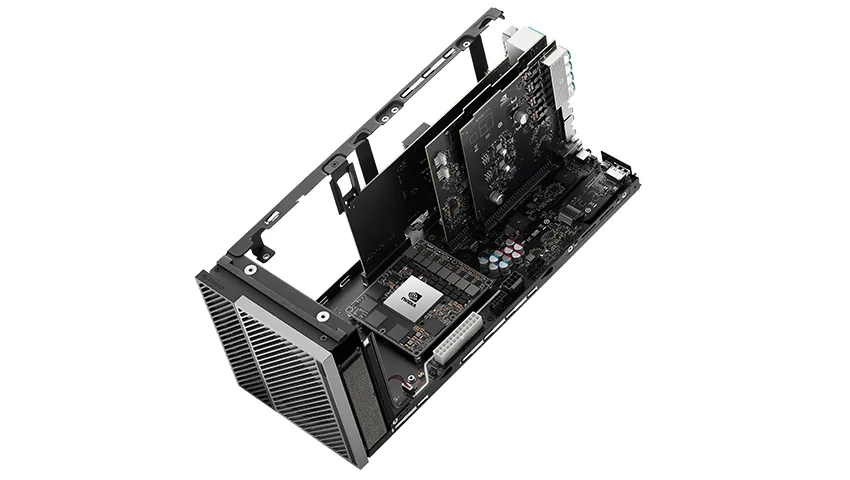
NVIDIA Jetson AGX Orin (~275 TOPS)Real-time LinuxSafety MCURedundant power
Hardware
Sensors & Actuation
Camera arrayLiDAR77 GHz radarRTK-GNSS / IMUDrive-by-wire
Safety & Compliance

Safe by design, not by exception.

Autonomy in a working terminal only earns its place if it is demonstrably safe. We treat functional safety as a first-class engineering requirement at every layer of the stack.

Designed-in redundancy

Independent sensing, compute, power, and braking paths so no single fault can remove the vehicle's ability to stop safely.

Independent safety monitor

A separate, isolated channel validates every motion command against geofences and proximity limits, outside the main compute path.

Minimal-risk condition

On any detected fault the vehicle executes a controlled stop to a known-safe state, backed by a hardware emergency stop.

Human-in-the-loop rollout

Staged deployment keeps trained operators supervising until the system has demonstrably earned trust in the real environment.

Geofenced operation

Vehicles operate only within mapped, approved operational design domains, with speed and behavior bounded per zone.

Auditable telemetry

Every mission is logged with full sensor and decision telemetry for traceability, incident review, and continuous improvement.

Engineered toward ISO 26262 (Functional Safety)ISO 21448 (SOTIF)ISO 3691-4 (Driverless industrial trucks)IEC 61508ISO 9001
Applications

Built for every corner of the terminal.

One autonomy platform, adapted to the full range of port and wharf operations, from the quay edge to the yard and the gate.

Quay & Berth Operations

Autonomous transport between quay cranes and the yard, with precise berth-edge maneuvering inside active crane envelopes.

Container Yard Handling

Coordinated stacking, retrieval, and horizontal transport across high-density storage blocks with minimal idle time.

Terminal Tractors & AGVs

Retrofit and purpose-built autonomous tractors and automated guided vehicles for repetitive intra-terminal haulage.

RoRo & Vehicle Decks

Low-speed precision movement for roll-on/roll-off operations where clearances are tight and traffic is mixed.

Intermodal Transfer

Rail-to-yard and gate-to-stack continuity that keeps containers moving across modal handoff points.

Charging & Service Cycles

Self-scheduled charging and return-to-service so fleet availability stays high without manual intervention.

Concept Breakdown

Capabilities, mapped to the terminal.

Each concept below maps to a specific capability area in autonomous port and wharf operations.

FAQ

Frequently asked questions.

Straight answers on how the platform is built, deployed, and operated safely.

Do you build the vehicles or just the software?
Both. We develop the full autonomy stack (perception, planning, control, and fleet software) and integrate it onto purpose-built platforms as well as retrofitted terminal tractors and AGVs.
How do the vehicles operate safely around people?
Through overlapping, multi-modal sensing, traffic segmentation between manned and autonomous zones, conservative speed envelopes, and an independent safety monitor that commands a controlled stop on any anomaly, backed by a hardware emergency stop.
What happens in fog, rain, or dust?
The sensor suite is intentionally redundant. When cameras and LiDAR degrade in poor visibility, 77 GHz radar maintains object tracking and closing-speed measurement, and the planner adapts speed and spacing accordingly.
Can the system integrate with our existing terminal operating system?
Yes. The fleet layer is designed to connect with existing TOS and yard-management systems for mission dispatch, scheduling, and live telemetry, rather than replacing them.
How are deployments rolled out?
In four stages: site assessment and mapping, integration and calibration, supervised autonomy with operators in the loop, and full autonomous operation with 24/7 monitoring. Each stage gates on demonstrated safety before the next begins.
Is the technical information on this site final?
No. The specifications, diagrams, and concept renderings are illustrative and forward-looking. They represent our design direction and may change as platforms mature.

Contact

Deploy autonomous vehicle systems at terminal scale.

For collaboration, pilot deployments, and integration planning across port and wharf environments, reach out to our team. We typically respond within two business days.

Prefer email? Write to contact@generalaxisrobotics.com.